


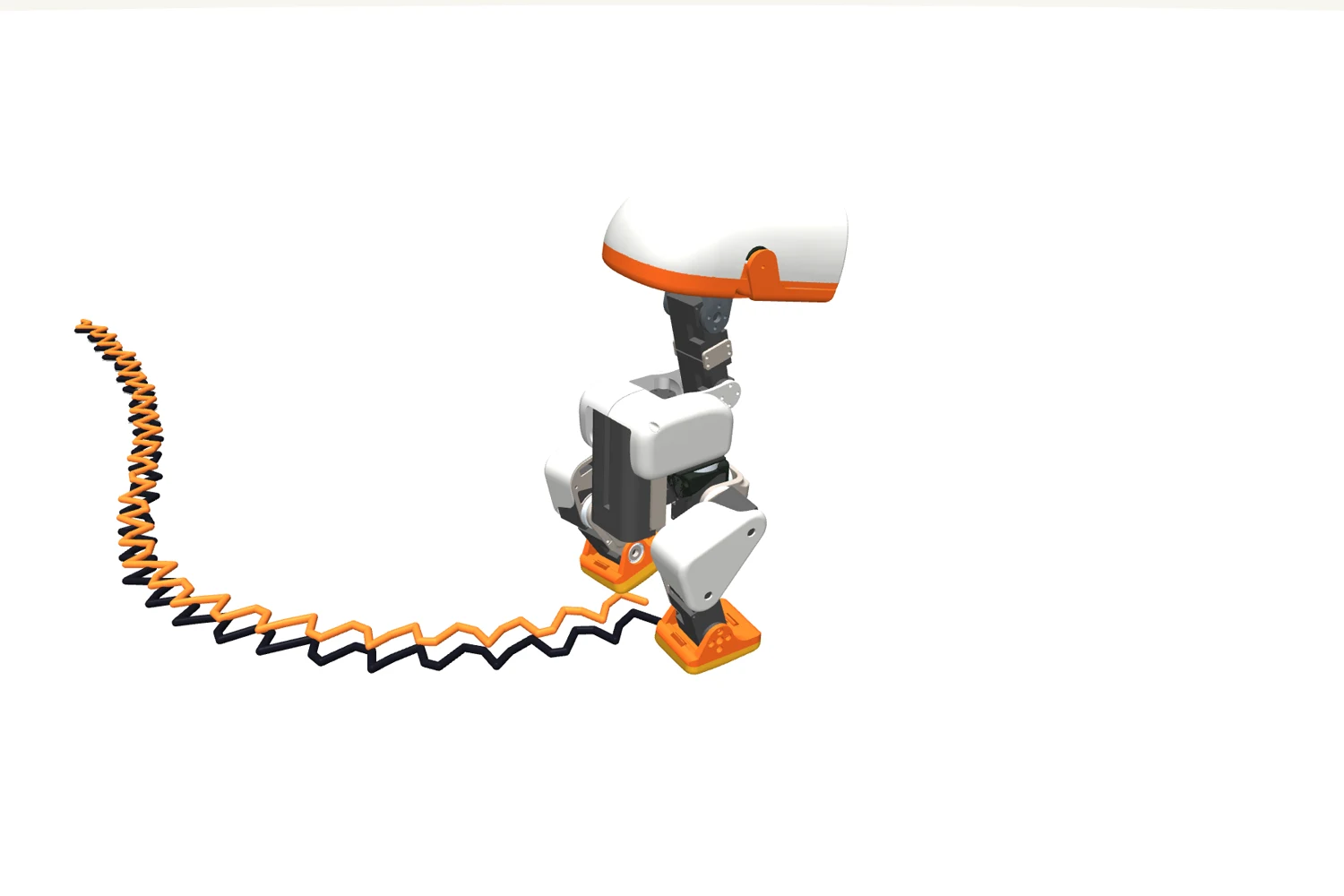

When Microduck walks across the office, the monitoring tool draws a little trail of where the robot thinks it has been. The robot has no wheels to count turns on, no external camera, and an IMU that is good at orientation and hopeless at position. The trail comes from about 200 lines of Rust that run once per tick of the 50 Hz control loop, and they rest on one observation: at any moment, some point of one of the two soles is touching the floor.
This post is about that code. Where the idea comes from, the one line of maths in it, when the estimator decides a step has happened, and how far the estimate is from the truth after a few metres of walking.
Twenty-five seconds of walking in the MuJoCo twin, driven by the real walking policy. The black trail is where the trunk actually went, the orange one is what the odometry believes.
Why not just integrate the IMU?
The first suggestion is always the IMU. It has an accelerometer, acceleration integrates to velocity, velocity integrates to position. The trouble is what happens to a small constant error along the way. Subtract gravity slightly wrong, or carry a slightly wrong bias, and the position error grows with the square of time:

Here p is the robot's position, so p̈ is its acceleration in the world. The accelerometer measures ameas in its own frame, R turns that into the world frame using the orientation the IMU also estimates, and g is gravity, which the accelerometer feels all the time and which has to be subtracted. A small error δa in any of that, whether a bias of the sensor or a slightly wrong R that leaks some gravity into the horizontal, becomes a position error δp that grows as t².
A 0.05 m/s² bias is a good day for a hobby-grade IMU. After ten seconds it has moved the estimate by 2.5 m, on a robot that walks at 0.15 m/s and has actually covered 1.5 m. So we don't ask the IMU for position at all. Orientation it does well, gravity fixes roll and pitch and the gyro holds yaw for minutes at a time, and that is all we take from it. Position comes from the legs.
The idea: one point is always on the ground
A walking robot always has at least one foot on the floor. Pick one point of that sole and call it the anchor. Its height is known exactly, since it is on the floor, so z = 0. Its x and y are wherever it was when it landed. From there the leg's joint angles tell you, through forward kinematics, where the trunk is relative to the anchor, and the IMU tells you which way the trunk is tilted. That is the whole estimator. Nothing is integrated, and the anchor only ever moves when another part of a sole gets lower than it, which is what a step looks like from the robot's point of view.
Side view. The teal dot is the anchor, the pink arrow is where the leg's joint angles put the trunk as seen from it, and the orange line is the trunk path this produces. Each time a foot lands, the anchor hops to it.
None of this is our invention. Rhoban's humanoids have used contact odometry of this kind in
their model_service for years, and our
odometry crate is a port of
it. It reads the leg geometry from the same MJCF file the walking policies are trained in, so the
estimator and the simulator cannot disagree about the length of a shin.
The math is one line
Three quantities go into it.
The first is c, the arrow from the trunk to the contact point, as the trunk sees it. Put a little coordinate frame on the trunk, x forward, y left, z up, moving and tilting with the body. Where is the foot touching the floor, in that frame? That only depends on the joint angles of the leg, q, the five motor positions from hip to ankle, and on the leg's dimensions. Computing it is what forward kinematics, FK, does:

The second is R, the trunk's orientation in the world. It comes straight from the IMU, as a quaternion: the IMU fuses its own accelerometer and gyro on board and reports the result. It is a rotation: applied to an arrow expressed in the trunk's frame, it gives the same arrow in the room's frame. So Rc is the arrow from the trunk to the foot, in room coordinates.
The third is a, the anchor: the contact point's position in the room. Its z is 0 because it is on the floor, and its x and y were fixed when that point touched down (the next section is about how).
The trunk position p is then one step back along the arrow. Start at the anchor, and go up the leg to the trunk:
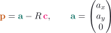
Step by step; pause it at any step. The anchor a is fixed on the floor. c is measured along the trunk's own axes, so it does not change when the whole body tilts; Rc, the same arrow in the room, does. Bending the leg changes c, tilting the trunk changes R, and either way p, found by walking back from a along Rc, follows.
Two things come for free. p includes the trunk's height above the floor. And nothing is added up over time, so a robot standing still stays exactly where it is: no drift while it is not moving.
Heading is the one quantity we do take from the gyro, as the yaw of the IMU's orientation. There
is no magnetometer, so "forward" is whichever way the robot was facing when it booted.
Everything that consumes this odometry, from the trail in robotctl monitor to the mapping
stack, treats it as relative motion and nothing more.
When does the anchor move?
The part that took some care is deciding which point of which sole is the contact. A sole is not a flat plate: on the alpha version of Microduck, the one we are testing now, it has bevelled edges and a slightly curved underside, and a walking foot rolls over it from heel to toe, so the actual contact wanders over the whole footprint during one stance. We sample the sole mesh at 16 points per foot, a 4 × 4 grid over the full footprint with the bevels included, and every tick we compute where all 32 of them are in the world, using the current estimate and the same forward kinematics:

ki is one of the sampled points, fixed on the sole, and FK(q) now places the whole foot rather than one point of it, so FK(q) ki is where that point is in the trunk's frame. Rotated by R and added to the trunk position p, it becomes wi, the point's position in the room, and wi,z is its height above the floor.
The anchor is at z = 0 by construction. If some other point comes out below zero, the robot has put part of a sole lower than what we were calling the floor, so that point is the real contact now. It becomes the anchor, and it keeps the world x and y it already has:

Keeping the old x and y is what makes the estimate continuous. The new anchor is placed exactly where the previous estimate said that point was, so the trunk does not jump at the switch. Whatever error was made during the previous stance, a foot that slid a little, a sampled point that was not quite where the sole really touched, gets frozen into the new anchor. It is never corrected, and it is never amplified either.
The rule, one tick at a time, with five sampled points per sole for clarity. On the right, each point's height above the anchor's plane as the estimator computes it. A point that stays under the plane for two ticks becomes the anchor: first as foot A rolls from heel to toe, then on foot B when it lands and A lifts. A point under for a single tick, a glitch, changes nothing.
The "two ticks" is 40 ms at 50 Hz, and it exists because forward kinematics on measured joint angles jitters. Without it, a one-tick glitch that pushes a point half a millimetre under the floor moves the anchor around in the middle of a stance, and the estimate picks up a little random walk. Two ticks is well inside a stance phase and well past a glitch.
The feet at quarter speed, drawn see-through. Grey dots are the 16 sampled points of each sole; one turns pink when it drops under the floor and bids for the anchor. The anchor is the larger teal ball. It walks from heel to toe across a sole as the foot rolls, and jumps to the other foot when that one lands.
In the 25 s run above the anchor moved 633 times, and only 122 of those were from one foot to the other. The rest were hops between points of the same sole while the foot rolled over it. A flat four-corner model of the sole would have had to pretend the contact stayed put while the foot rocked, and every millimetre of that pretending goes straight into the trunk estimate.
What it costs, and how wrong it gets
The estimator runs inside the control loop, on the joint positions and IMU quaternion the loop has just read for the policy, so it adds no bus traffic. Per tick it evaluates two kinematic chains, one per foot, and pushes 16 points through each, which is about a microsecond.
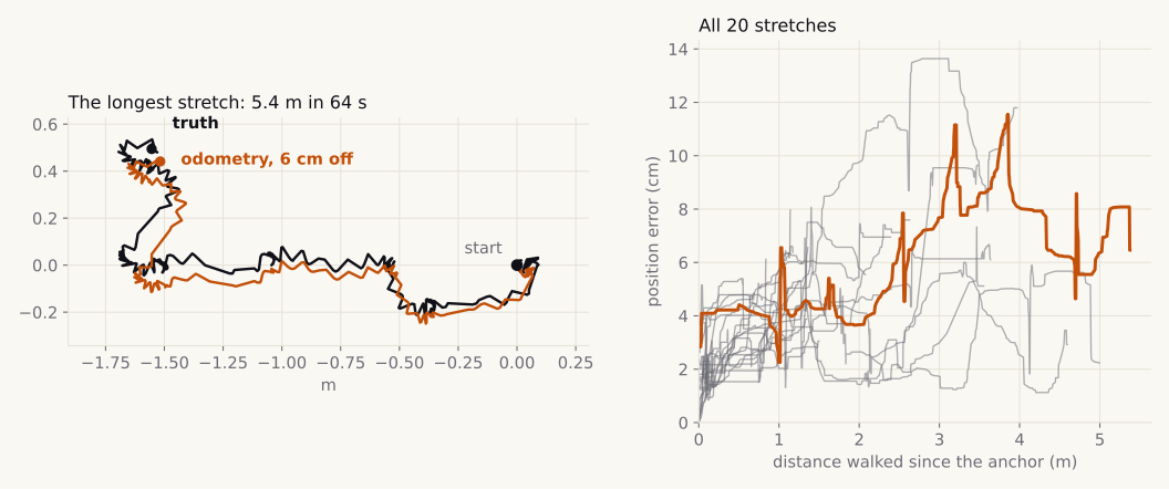
How wrong does it get? We measured it on a real duck, walking around a living room driven from a pad, against a ground truth: eight ArUco tags taped to the floor, a fixed 4K camera in the corner, and a small tag on the duck's head, which the camera places to about a centimetre. The duck never sees any of this; we built the rig for the mapping work, and the recordings are public in the SLAM_JJ_Salon_with_GT dataset.
The longest stretch, about 3× sped up: 5.4 m in a minute, with a lot of turning in place. Green is where the camera says the trunk went, blue is the odometry, both anchored at the start. It ends 6.5 cm off.
The two recordings hold about nine minutes of walking, broken into twenty stretches by the moments the duck was picked up, sat down or fell, since each of those is a jump odometry cannot see. We anchored the odometry on the truth at the start of each stretch and followed it to the end.
| over 20 stretches, 47.5 m in total | median | worst |
|---|---|---|
| position error at the end of a stretch | 5.7 cm | 11.8 cm |
| as a share of the distance walked | 2.9 % | |
| heading error at the end of a stretch | 1.8° | 4.5° |
Over all the walking together the error is 2.4 % of the distance, and the longest stretch, 5.4 m in a minute, ended 6.5 cm off, 1.2 %. That is about twice what the simulator predicts, which is what we expected: the real feet slip more than the simulated ones, and these were driven walks, with a lot of turning in place, the motion that costs the most.
The simulator is where we can see when the error is made, since there the same code runs against a body whose position we know exactly:
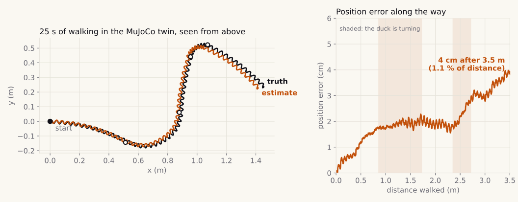
Most of the error comes from the one assumption the estimator makes, which is that the contact point does not move. During a sharp turn the stance foot scrubs on the floor, and every millimetre it slides is a millimetre the trunk did not actually travel. On the straight sections the error creeps up much more slowly, from the sampled points not sitting exactly where the sole really touches, a few millimetres per step in a direction that depends on the heading, which partly cancels over a long walk and does not over a short one.
The other source is heading. The simulated IMU has a perfect yaw, which is why the chart shows no rotation of the path at all. On the real duck the heading was off by 1.8° at the end of a stretch, on median, after up to a minute and several full turns, and 4.5° at worst. Small as it is, a heading error rotates every step that follows it: 2° is 3.5 cm of sideways error per metre walked afterwards, and over the longer stretches it is a good part of what the camera measures.
What this odometry is not
It is not a position in the room. It tells you how the robot moved since it booted, and it will be more wrong the longer it walks. Anything that needs to know where the duck is, rather than how far it went, has to look at the world with something else. On Microduck that is the depth sensor and the mapping stack. They don't throw the odometry away; they fix it whenever they recognise where the duck is. That is a post of its own.